[2008-08-08] DIY PVC benchtop gas generator after Kipp
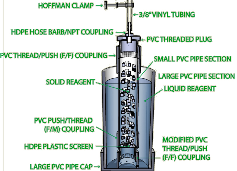
A Sketchup file showing the completed generator is here.
If you should find yourself in need of small volumes of gas at about atmospheric pressure for a reaction or project, generating it on the bench can be a convenient and inexpensive alternative to buying or renting a gas cylinder. It turns out there are a number of useful gas-generating reactions between solid- and liquid-phase reagents, such as:
- Hydrogen: Zn + HCl —> ZnCl + H2
- Acetylene: NaC2H + H2O —> NaOH + C2H2
- Carbon dioxide: CaCO3 + HCl —> CaCl + CO2
- Hydrogen sulfide: FeS + H2SO4 —> FeSO4 + H2S
An all-glass reactor was designed for this purpose in the 19th century by Petrus Jacobus Kipp, who is known today primarily for this achievement. Kipp's design incorporates the clever feature that stopping the flow of gas separates the liquid and solid reagents inside the instrument and thereby stops the reaction. Thus the generator only produces gas when you need it, and may remain in a stable equilibrium state on the bench for days at a time, ready to resume operation as soon as you open the valve.
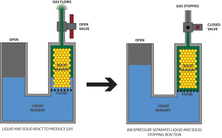
Essentially, the generator consists of a closed chamber, loaded with solid reagent, which communicates with a liquid reagent reservoir at one end, and from which gas escapes at the other. The liquid reservoir is open to the atmosphere, and thus the pressure of gas generated is limited by the hydrostatic pressure of the reservoir column. When the gas valve is closed, gas pressure backs up in the chamber and pushes the liquid reagent back out of the chamber, where the solid phase is retained, thus halting the reaction. Excess gas bubbles out into the atmosphere through the liquid reservoir. Safe technique, of course, demands that any use of gas be conducted in a well-ventilated area, but there is no plausible danger of a pressure explosion.
Being made of glass, however, a proper Kipp generator is an expensive piece of apparatus, with new models costing upwards of $250US as of this writing. However, as the useful gas-generating reactions are inevitably aqueous, rather than organic, there's no reason why an all-plastic Kipp generator cannot be entirely adequate to its purpose. PVC pipe is inexpensive, durable, ubiquitous, and easily and securely joined using cement made for that purpose. Demountable PVC fittings are available in a wide variety of shapes and sizes and can be used to provide the necessary "dismantlability" for loading solid reagent into the device. Presented on this page is my design for such a low cost Kipp generator, with instructions for its construction.
My design features a "radial" construction which, albeit slightly more complex than the obvious "u-tube" design shown above, offers several advantages over it, in my opinion. First and foremost of these is that the radial design makes it possible to remove the chamber full of solid reagent without removing the liquid reagent first. So, if necessary, the chamber can be removed and reloaded without the hassle of pouring off the liquid phase. Also, the radial design is self-stabilizing and stands up on its own without the need for auxiliary supporting means. On the down side, the radial design tends to limit the height of the liquid reservoir, which in turn limits the gas pressure which the device can produce. If you want a Kipp generator that will operate at pressures much greater than the atmosphere, the u-tube design would probably be better. A plastic J-bend for plumbing a residential sink might be a good starting point for such an effort.
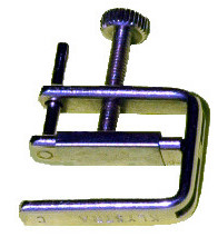
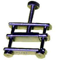
Gas valving is provided by a Hoffman-type screw clamp which compresses the vinyl tubing where it exits the reaction chamber. These clamps can be readily and inexpensively purchased online. The Hoffman clamp is the only component that cannot be had from a well-stocked hardware store. If one were really reluctant to send away, it would not be a terribly difficult thing to build for oneself. I've experimented along these lines myself, and have attempted to use bulldog clips and thumbscrew window sash-locks as improvised compression valves without appreciable success. A proper Hoffman clamp is inexpensive and, in my opinion, well worth the slight inconvenience of mail-order.
The complete bill of materials and tools is:
- 1 Hoffman-style compression clamp
- appropriate length of 3/8" vinyl tubing
- 1 9.5" length of 4.5" outer diameter PVC pipe
- 1 5" pipe cap to fit above
- 1 8.25" length of 1.75" outer diameter PVC pipe
- 2 threaded/push-fit (F/F) couplings for 1.75" pipe
- 1 threaded/push-fit (M/F) coupling for 1.75" pipe
- 1 threaded plug to fit F/F coupling
- 1 ~1/16" thick plastic disc 1.75" in diameter
- 1 1/4" hose barb / 3/8" NPT male threaded coupling
- PVC pipe cement, preferably of the gap-filling variety
- Acetone or alcohol to clean PVC components beforecementing
- Hand saw
- Step drills up to 9/16" diameter
- 3/8" NPT tap or threaded fitting
- Appropriate wrench for the above
- 1/2" or wider wood chisel, or other sharp edge
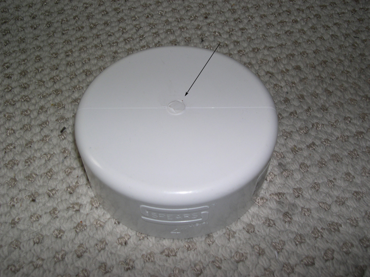
First, remove the raised mold mark from the center of the PVC pipe cap so that it will rest flat on a surface. I used a sharp wood chisel and hand pressure for this operation.
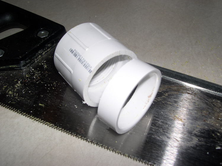
Second, modify one of the two F/F couplings by sawing through it about halfway along the length of the unthreaded end. The purpose of this is, first, to expose a larger surface for cementing the butt joint between the coupling and the large pipe cap, and second, to reduce "dead height" at the base of the reaction chamber.
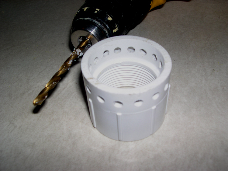
Third, modify the same coupling further by drilling a series of ~3/16" holes around the freshly-cut edge, as shown in the photo. These holes allow the outer liquid reservoir to communicate with the inner reaction chamber. I drilled 16 of them, evenly spaced around the coupling's circumference.
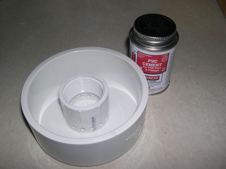
Fourth, center the modified coupling inside the large pipe cap and cement as shown. The great thing about PVC cement is that the joints it makes are incredibly strong. You don't have to worry about this butt joint breaking loose.
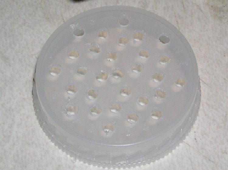
Next, prepare the filter element which will keep the solid reagent from falling out the bottom of the reaction chamber. I used the polyethylene liner of an old vitamin-bottle cap, but in truth any appropriately sized disc of plastic will work. Drill a bunch of ~1/8" holes in it as shown.
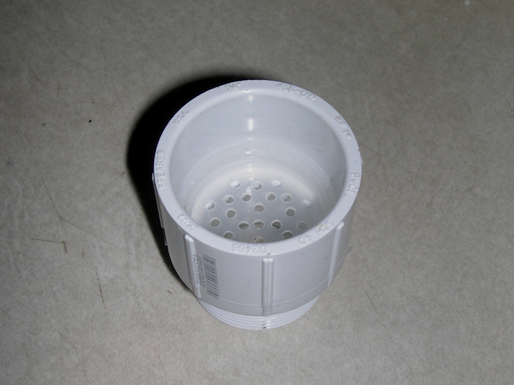
Now assemble the reaction chamber parts. Put the filter in place inside the push-fit end of the F/M coupling, as shown, then cement the small pipe section in place on top of it, securing it in position. Cement the push-fit end of the unmodified F/F coupling to the pipe's other end.
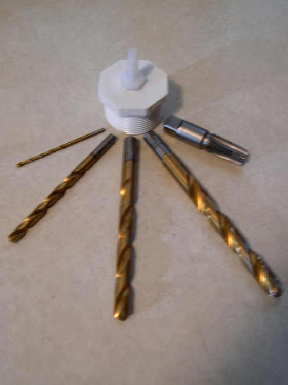
The next step is to install the hose barb in the threaded PVC plug. The coupling is blah by blah. I step-drilled up to 9/16" and then tapped the hole with a 3/8" NPT pipe tap. The tap was not expensive, but if you want a cheaper alternative you can always by a metal pipe fitting of the proper thread and use it instead of a proper tap on the relatively soft plastic. Apply PVC cement to the barb's threaded end and tighten it into the hole. Test this joint for gas tightness by closing the barb with your fingertip and filling the inverted plug with water. None should seep from the glued joint. If it does, apply more cement to the inside of the joint and repeat the test.
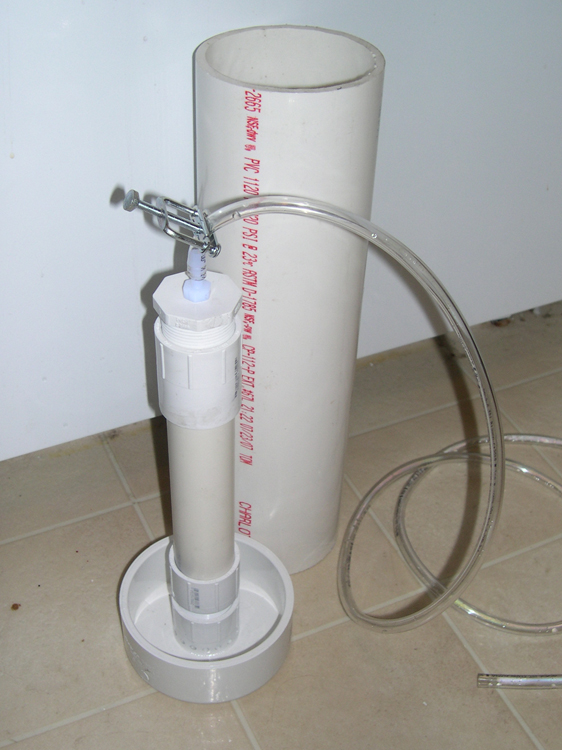
The final step is to cut the large diameter pipe section to an appropriate length and cement it in place inside the large pipe cap, as shown. Fill the assembly with water and let stand overnight to test the joint you just made.
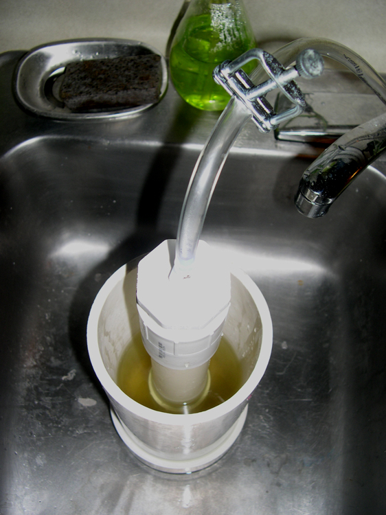
To use the generator, fill the reaction chamber with your solid reagent (e.g. limestone or marble chunks) and screw in the threaded plug to seal the top end. Thread a length of 3/8" vinyl tubing through your Hoffman clamp and attach it to the hose barb. Now screw the bottom end of the reaction chamber assembly into the coupling in the bottom of the liquid reservoir and fill it with your liquid reagent (e.g. pool acid), leaving a couple of inches headspace at the top to allow for possible bubbling. When the Hoffman clamp is opened, gas should begin to flow through the tubing in a few seconds. You can easily test for this by submerging the end of the tube in a bowl of water. When you close the clamp, back pressure from the generated gas will drive the liquid phase down and out of the reactor assembly, causing the gas-generating reaction to stop in short order. Some excess gas may bubble up through the liquid reservor, but it should not continue for very long. Now you should be able to leave the generator in place indefinitely, so long as your liquid reagent does not evaporate, and it will remain ready to produce gas whenever the Hoffman clamp is opened.
last modified 2008-08-08